|
Calibration
SETTING
THE ALARM POINTS - MOS SENSORS:
The
sensor should be allowed to warm up and stabilize for 24
hours before setting alarm points.
Method
using DVM and Calibration gas.
- Connect
voltmeter negative probe to the REF (Black) test point.
Connect the positive probe to the YELLOW test point corresponding
to the sensor being calibrated.
- Apply
low alarm calibration gas, at the appropriate rate, to
the sensor and note the maximum voltage reading. (Takes
1 ½ to 2 minutes).
- Connect
voltmeter positive probe to the RED low alarm test point
of the sensor being calibrated and set the voltage to
the value noted in Step 2. Low alarm is now set for that
sensor.
- Repeat
steps 1 to 3 using high alarm calibration gas and high
alarm test point.
- Repeat
steps 1 to 4 for second sensor.
Method
using calibration gas only.
The
alarm points can be adjusted and set at any time while the
CT-2100 is powered and ON. If the unit is in alarm, turn
the alarm trimpot you wish to adjust (counterclockwise)
until it comes out of alarm. Alarm settings should always
be made from an out-of-alarm state to an alarm state.
- Through
a humidifier (see Calibration Kit
drawing), apply a calibration gas mixture to the sensor
equal to the level required for the LOW alarm point. Allow
1 ½ to 2 minutes for sensor to stabilize.
- Adjust
alarm 1 (LOW) so that the relay 1(LOW) LED comes on. (Red
LED on front cover).
- Repeat
for alarm 2 (LOW).
- Through
a humidifier (see Calibration Kit
drawing), apply a calibration gas mixture to the sensor
equal to the level required for the HIGH alarm point.
- Adjust
alarm 1 (HIGH) so that the relay 1 (HIGH) LED comes on.
(Red LED on front cover).
- Repeat
for alarm 2 (HIGH)
Calibration
Gas Flow Rates:
- MOS
Sensor 0.4 SCFH (0.2 LPM)
- NO2
Electrochemical Sensor 2.0 SCFH (1 LPM)
SETTING
THE ALARM POINTS - 2-WIRE, 4-20mA OUTPUT SENSORS:
Sensor
+ 12 VDC and Signal Return are connected to the 2 pin sensor
input connector as shown below. On AirTest 4 - 20 mA transmitters
there is no need to observe the polarity.
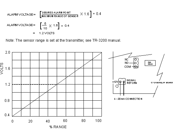
When
equipped with a 4 - 20 mA input capability, the CT-2100
is factory set so that 0.4V equates to 4 mA and 2.0V equates
to 20 mA. ( Measured at REF (Black) negative Test Point
and ZERO/SPAN (Yellow) positive Test Point.
To
set the alarm points, connect negative probe of voltmeter
to REF (Black) Test Point and positive to LOW or HIGH (Red)
Test Point. Set the voltage with corresponding alarm trimpot
to read the value obtained from the graph below.
The
graph displays voltage on the vertical axis (0.4V to 2.0V
corresponding to 4mA to 20mA) and transmitter range on the
horizontal axis ( 0 to 100%).
e.g.
An NO2 sensor with a range of 0 - 10 ppm is connected at
the transmitter. An alarm point of 5 ppm is desired, this
is 5/10 = 50% of range. 50% of range = 1.2V Set alarm voltage
at 1.2V
Or,
using the formula:
Figure
1
SETTING
THE ALARM POINTS - 3-WIRE, 4-20mA OUTPUT SENSORS:
Sensor
+ (pos) and SIGNAL are connected to the 3 pin sensor input
connector. The sensor - (neg) is connected to the 2 pin
sensor input connector. Connections are shown below.
When
equipped with a 4 - 20 mA 3-wire input capability, the CT-2100
is set up so that 0.8V equates to 4 mA and 4.0V equates
to 20 mA. ( Measured at REF (Black) negative Test Point
and ZERO/SPAN (Yellow) positive Test Point.
To
set the alarm points, connect negative probe of voltmeter
to REF (Black) Test Point and positive to LOW or HIGH (Red)
Test Point. Set the voltage with the corresponding trimpot
to read the value obtained from the graph below.
The
graph displays voltage on the vertical axis (0.8V to 4.0V
corresponding to 4mA to 20mA) and transmitter range on the
horizontal axis ( 0 to 100%).
e.g.
An LEL sensor
with a range of 0 - 100 %
LEL is connected at the transmitter. An alarm point
of 20 % LEL is
desired, this is 20/100 = 20% of range. 20% of range = 1.44V
Set alarm voltage at 1.44V
Or,
using the formula:
Figure
2
Figure
3 - MOS SENSOR
CALIBRATION KIT
Figure
4 - RELAY TIME DELAY SETTINGS

|


 The
CT-2100 is a dual input monitor for stand-alone applications.
It is normally supplied with one onboard


