Carbon Dioxide Sensor AirTest Model TR-9200 |
 |
|
TR-9200 - 4-20 mA Sensor / Transmitter The AirTest TR-9200 is a non-dispersive infrared analyzer for measuring environmental CO2 (Carbon Dioxide) concentration in ventilation systems and indoor living spaces. measurement range of 0 - 5000 ppm covers the range required to monitor compliance with ASHRAE or other ventilation efficiency standards. The TR-9200 provides several output alternatives. A voltage or 4 - 20 mA current output is standard. An optional LCD readout is available. An optional relay contact can be configured to open or close above a user-adjustable setpoint. A simple one-point calibration procedure and a built-in calibration port that requires no special fittings or adapters make the TR-9200 simple to maintain. |
||||||||||||||||||||||||||||||||||||||
 Top |
||||||||||||||||||||||||||||||||||||||||
|
|
|
AirTest continues to work on product improvement, specifications are subject to change without notice. |
||||||||||||||||||||||||||||||||||||||
|
Top |
||||||||||||||||||||||||||||||||||||||||
|
|
|
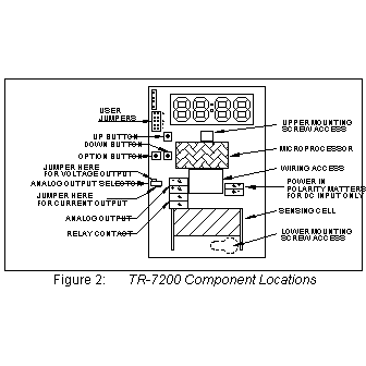
To open the TR-9200 use a coin in the slot on the bottom to release the snap. Lift the cover up slightly to disengage the closure and remove cover with a downward motion to clear the catch at the top of the unit. The locations of controls and terminals on the main circuit board are shown in Figure 2. Mounting The TR-9200 is designed for flush mounting with two fasteners. The locations of the mounting points (shown in Figure 1) allow direct mounting on a standard simplex (single circuit) junction box. There is a wiring cutout in the center of the unit near the terminal strips.
Wiring This section describes the external connections to the TR-9200. Wiring enters the chassis through the cutout in the center of the unit.
Power Supply The TR-9200 will operate from an AC or DC input voltage between the values called out in the specifications. The power supply leads are connected to the two-terminal power connector shown in Figure 2. The TR-9200 must never be connected directly to line power. Operation at voltages higher than specified will damage the unit and void the warranty. When operating from DC power, the polarity of the power leads must be as shown in Figure 2. Reversed polarity connection will not damage the unit, but will make it inoperable until the connection is reversed. Signal Output The TR-9200 provides either a 0 - 10 volt or a 4 - 20 mA current loop output at the two terminals of the analog output connector shown in Figure 2. The type of analog output is determined by the setting of the analog output selector shown in Figure 2. The analog output of the TR-9200 is completely isolated from the power supply. The common outputs of multiple units can be connected together with no interaction regardless of power supply hook-up. Voltage When the outboard and middle pins of the analog output selector are connected with the shorting block, a voltage output appears between the two terminals marked ANALOG OUTPUT. The output voltage increases linearly from 0 volts at the low output threshold to 10 volts at the high output threshold. The unit is shipped from the factory with the low output threshold at 0 ppm and the high output threshold at 2000 ppm. See the Analog Output Range Adjustment section to change the analog output range limits. Current When the inboard and middle pins of the analog output selector are connected with the shorting block, a current output appears between the two terminals marked ANALOG OUTPUT. The output current increases linearly from 4 mA at the low output threshold to 20 mA at the high output threshold. The unit is shipped from the factory with the low output threshold at 0 ppm and the high output threshold at 2000 ppm. See the Analog Output Range Adjustment section to change the analog output range limits. If the total resistance between the two terminals exceeds the specified maximum loop resistance, the output current may be erroneously low at high concentrations. Verifying Voltage or Current Output Connection After the voltage or current output of the TR-9200 is connected to a controller or indicator, the following check should be performed to ensure that the connection has been properly established and the TR-9200 is transmitting the correct values:
Cover Replacement Engage the top center of the cover under the latch at the top of the base, then press the bottom of the cover onto the base until it latches. Field Adjustments This section describes the features that can be field configured and the procedures to make these changes. Analog Output Range Adjustment This section refers to advanced features of the TR-9200. 2000 ppm users need not perform this adjustment. The TR-9200 ships from the factory set for an analog output range of 0 to 2000 ppm. This range can be changed to any sub-range between 0 and 5000 ppm by changing two parameters:
For example, a particular application may require the analog output to remain at 0V or 4.0 mA until the gas concentration reaches 500 ppm, then reach 10V or 20 mA at a concentration of 1000 ppm. In this example the analog output would scale across this 500 ppm sub-range so that the analog output would be at half scale (5V or 12 mA) at 750 ppm. To change the analog output range use the following procedure:
Altitude Correction The TR-9200 is factory-calibrated for operation at sea level. When operated at higher elevations, the calibration must be adjusted by the amount shown in the altitude correction table to the right. Altitude Correction Procedure To adjust the calibration of a unit currently calibrated for sea level operation to a new altitude proceed as follows:
|
||||||||||||||||||||||||||||||||||||||
|
Top |
||||||||||||||||||||||||||||||||||||||||
|
|
|
This section describes the calibration verification procedure and calibration adjustment procedures. Verification Procedure A quick but approximate calibration verification can be done by supplying the unit with outside air and letting the reading stabilize. CO2 concentrations in outside air are typically between 350 and 450 ppm. A more accurate calibration check requires the use of calibration gas of known concentration. A calibration kit is available from the factory. To verify the TR-9200's calibration, proceed as follows:
High CO2 Limit An adjustable high CO2 limit is a standard feature of the TR-9200. The front panel LED changes from steady to blinking when the indicated concentration is above the high CO2 limit value. An optional contact closure is available which opens or closes when the high limit is exceeded. Adjusting the High CO2 Limit The setpoint value is adjusted by closing jumper JP3 (see Figure 2 on page 2). If the display is present when JP3 is closed it will show the current high limit setpoint in ppm CO2. If there is no display this setting can be adjusted by using a meter connected to the output. In this calibration mode the analog output is 10,000 ppm at full scale (i.e. 10.0 volts or 20.0 mA). If the voltage output is selected, this scaling corresponds to 1ppm per millivolt or 1 volt per 1000 ppm. The setpoint is adjusted with the 'UP' and 'DOWN' ../buttons while JP3 is closed. When JP3 is opened, the new relay setpoint takes effect and is stored in non-volatile memory. The setpoint hysteresis is approximately 40 ppm. Optional High Limit Contact The high CO2 limit option provides a dry (i.e. unpowered) contact closure that activates when the detected concentration rises above the high CO2 limit. The high limit is adjustable from 0 to full scale of the unit Setting High Limit Contact Polarity The polarity of the high limit contact is set with jumper JP5 as shown in the table below.
To open jumper JP5 remove the shorting block from the two pins, and replace it so that it engages only a single pin of the jumper. The shorting block should not be removed; it is required during the calibration procedure. |
||||||||||||||||||||||||||||||||||||||
|
Top |
||||||||||||||||||||||||||||||||||||||||
|
|
|
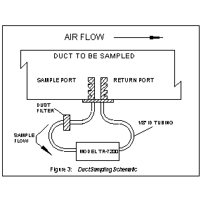
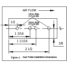
Overview The duct sampling option is used to divert a portion of the duct airflow through the TR-9200. The difference between the total pressure at the upstream sample port and the static pressure at the downstream return port propels the sample stream. Minimum recommended flow rate is 200 feet per minute. A TR-9200 with the duct sample option has a sample draw adapter fitted to the bottom of its enclosure. The duct probe assembly is connected to tubing nipples on the adapter. Duct Kit Contents
Duct Kit Installation
|
||||||||||||||||||||||||||||||||||||||
|
Top |
||||||||||||||||||||||||||||||||||||||||
|
|
|
AirTest warrants to Buyer of the AirTest TR-9200 that for 18 months from the date of shipment of Products to the Buyer that Products will substantially conform with the product specifications agreed to by AirTest. This warranty is not transferable. This warranty does not cover: Defects due to misuse, abuse, or improper or inadequate care, service or repair of Products; Defects due to modification of Products, or due to alteration or repair by anyone other than AirTest; or Problems that arise from lack of compatibility between AirTest' Products and other components used with those Products or the design of the product into which Products are incorporated. Buyer is solely responsible for determining whether Products are appropriate for Buyer's purpose, and for ensuring that any product into which Products are incorporated, other components used with AirTest' Products, and the purposes for which AirTest' Products are used are appropriate and compatible with those Products. The warranty in this section is in lieu of all other warranties, express or implied. AirTest expressly disclaims all implied warranties, including the warranties of merchantability and fitness for a particular purpose AirTest is not responsible in any way for damage to a product, property damage or physical injury resulting in whole or in part from (1) Improper or careless use, (2) Unauthorized modifications or (3) Other causes beyond the control of AirTest. In no event is AirTest liable to the buyer or any other person for cost of procurement of substitute goods, loss of profits, or for any other special, incidental or consequential damages. |
||||||||||||||||||||||||||||||||||||||
|
Top |
||||||||||||||||||||||||||||||||||||||||
|
|
|
|||||||||||||||||||||||||||||||||||||||
|
Top |
||||||||||||||||||||||||||||||||||||||||
|
|
 |
|||||||||||||||||||||||||||||||||||||||


|
361
Steelcase Road West
Markham, Ontario L3R 3V8 Tel.: (905) 477-2133 Fax: (905) 477-4219 Toll Free: (800) 567-8686 |
|
|