|
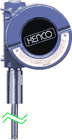 TRANSMITTER FEATURES
- CSA approved
explosion-proof housing
- Toggle switch
for zero and span settings
- Temperature
range: -30 to 300 degrees Fahrenheit (call KENCO for higher
temperature requirements)
- No maintenance
required
- Immune from
electrical and mechanical noise
- HART®
Communications available
KENCO LEVEL
TRANSMITTERS
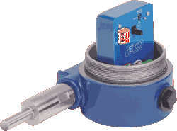
KENCO level transmitters
offer 4-20mA loop-powered circuitry for level measurement. The KENCO
transmitter is available up to a length of 300 inches. Zero and
span may be adjusted using a weather-resistant toggle switch. Zero
may be set at any location along the length of the transmitter with
100% zero suppression.
These transmitters operate within a process temperature range of
-30ºF to 300ºF for most lengths (see specifications).
Field replaceable electronics are potted and encapsulated. KENCO
transmitters are available as standard
with NEMA 4X/7 type electronics housings.
These housings feature an industrial epoxy coating for corrosion
resistance.
All KENCO level transmitters use non-contacting, magnetostrictive
technology.
This simple design ensures no scheduled maintenance or re-calibration
‹ever. Accurate, non-contact float location sensing is achieved
with absolutely no wear
to any of the sensing elements.
PRINCIPLE OF MAGNETOSTRICTION
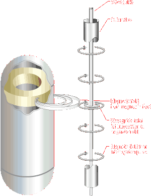 |
The level transmitter
is composed of two concentric members. The outermost member is a
protective 304 stainless steel chamber that withstands aggressive
or harsh process industry environments. The heart of the transmitter
design is the innermost member, the waveguide, a formed element
constructed of a proprietary magnetostrictive material.
A pulse is induced in the waveguide by the momentary interaction
of two magnetic fields, one from an electric current pulse launched
along the waveguide and the other from the magnet inside the float.
This interaction produces a strain pulse that travels along the
waveguide. The location of the magnet inside the float is determined
by measuring the elapsed time between the launching of the electronic
pulse and the detection of the strain pulse by the sensor head.
The time period measurement is used to produce a 4-20mA output.
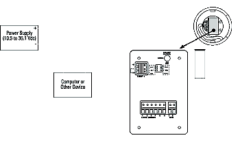
PRODUCT WIRING-EXPLOSION
PROOF APPLICATION
PARAMETER SPECIFICATIONS
LEVEL OUTPUT
- Measured
Variable Product
level
- Full Range
0.5
to 25 ft. (152 mm to 7.6 m)
- Non-linearity
Full span 0.100
% F.S. (Independent BSL) or 1/32 in. (0.794
mm), whichever is greater.
- Repeatability
0.01
% F.S. or 0.015 in. (0.381 mm), whichever is
greater.
- Temperature
Sensitivity Zero:
(0.003%/°F (0.005 %/°C)
- Sensor Operating
Temp. Operating
temperature is -30 to 300°F. Contact METEX
for higher temperature requirements
TRANSMITTER LOOP
- Input Voltage
Range
10.5 to 36.1 Vdc
- Reverse
Polarity Protection Series
diodes
- Safety Approval
CSA certified explosion-proof Class I, Division 1, Groups
B, C, and D
CALIBRATION
- Zero Adjust
Range
Anywhere within the active length
- Span Adjust
Range
FS „ 0.5 ft. (152 mm) from zero
ENVIRONMENTAL
- Sealing
Potted
sensor cartridge and electronics
- Humidity
0
to 100 % R.H.
- Operating
Temperature
-30 to 160°F (-34 to 71°C)
- Materials
304
stainless steel
FIELD INSTALLATION
- Transmitter
Length
Up to 25 ft. (7.6 meters)
- Wiring Two-wire
connection, shielded cable or twisted
pair to screw terminals through a 3/4 in. (12.7 mm)
NPT conduit opening
|
 |
 |
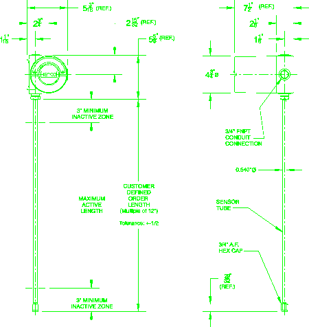
MOUNTING INSTRUCTIONS
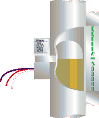
The KM/KH transmitter
is mounted directly to the housing of the KENCO Magnetic Liquid Level
Indicator. In a typical configuration, the magnetic flag assembly
and transmitter are attached to the gauge housing with mounting clamps
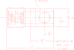
provided. Install the transmitter to the right or left of the flag
assembly by placing the transmitter sensor tube 90° away from the
flag assembly. Tighten the mounting clamps provided around the transmitter
sensor tube. Allow for a minimum inactive zone of 3 inches at the
bottom of the sensor tube by placing bottom of sensor 3 inches below
the zero setting (centerline of bottom gauge process connection).
Allow for a 3 inch inactive zone starting at the top as well.
NOTE: The transmitter head can be rotated 360° when mounted as shown
to the right.
NOTE: The transmitter may also be mounted with the transmitter head
at the foot of the gauge. Consult factory for specifics.
Back
To Top
Magna-Site
Accessories
EXPOLSION-PROOF HIGH-
or LOW-LEVEL SWITCHES
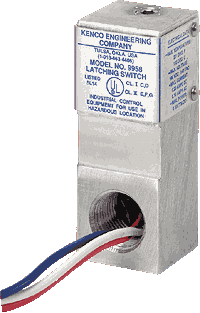 Mount Switch so that 1/2"
NPT connection
is below mounting clamp.
- Can activate alarms, pumps or
valves when the liquid reaches high or low levels.
- Does not come in contact with
process liquid

SPECIFICATIONS
HEIGHT
SCALES

- Standard scales are 304 stainless
steel with no.3 finish
- Standard scales show height in
feet/inches or meters/centimeters
- Large numerical characters offer
increased visibility
- Standard scale division marks/characters
are etched and paint filled
- Can be calibrated for any unit
of measure
INSULATION
BLANKET

- Withstands temperatures up to
750oF
- Standard shell material is 18
Teflon® cloth
- Also available in other materials
based on application
- Steam tracing also available

Back
|