|
TR-5500
- 4-20 mA Sensor / Transmitter
 Catalytic
bead technology is used as the sensing element in the TR-5500
Combustible gas (LEL)
Sensors. The sensor produces a response linear to the gas
concentration being detected. This sensor is used to monitor
combustible gases in areas classified as Class 1, Division
1, Groups B, C & D.
Specifications
| Installation |
Calibration | Dimensions
| Wire Diagrams
|
|
Calibration
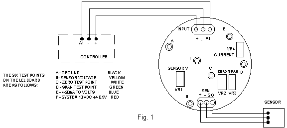
The
sensor/transmitter must be connected to the controller.
Allow the sensor three to five minutes to warm-up before
calibrating.
- Connect
negative lead of voltmeter to test point C. Connect positive
lead of voltmeter to test point D. Apply "zero"
gas to the sensor. (ambient air may be used if it is certain
there are no contaminants in the area). Adjust VR2 (ZERO)
to 0.0Volts ± 0.020V.
- Connect
negative lead of voltmeter to test point A. Connect positive
lead of voltmeter to test point E. Adjust VR4 (CURRENT)
to 0.400 Volts. If an ammeter is available it is preferable
to connect it in line A1 and adjust VR4 to read 4.00 mA.
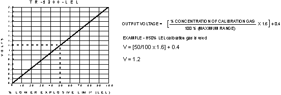
- Refer
to graph below, apply calibration gas to the sensor at
a rate of .5 LPM. Adjust VR3 (SPAN) to a voltage corresponding
to the % LEL
calibration gas used. The formula below can also be used
to determine the voltage value.
In the example, if 50 % LEL
calibration gas is used, the span voltage is 1.2 volts.
NOTE:
The system voltage, measured between point A (negative)
& point F (positive), is factory set. Do not change
this voltage value. The sensor voltage, measured between
point A (negative) & point B (positive), is factory
set and the value is sensor type dependent. Do not change
this voltage value. Damage to the sensor will result if
the voltage is set too high. For the TR-5500 this is 3.50
volts.
Figure
1
Figure
2
|


