|
|
| Flow
Rate Transmitters and Sensors |
|
|
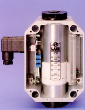 |
| • |
Simple
to Install: All
transmitters are factory calibrated and ship fully assembled.
Simply install the transmitter into your system and
apply power. |
| • |
Weather-Tight
Construction: The
sealed, corrosion resistant, enclosure allows installation
in environments where liquid tight seals are required.
|
| • |
Industry
Standard Outputs: Transmitters
provide proportional analog outputs of 4-20mA, 0-1mA,
0-5Vdc and 1-5 Vdc1. These outputs will drive
popular data acquisition devices, meters and analog
input cards. |
|
| • |
Rugged
and Reliable: Without
delicate internal components to break, abrade or corrode,
the Lake flow transmitter will provide many years of
low maintenance service. |
| • |
Direct
Reading or Optional Digital Display: All
transmitters provide a visual indication of flow rate
integral to the transmitted output. For improved readability,
an integral digital display is available. |
| • |
Compatible
With Lake Monitor's R100 & R/T100: The
Lake flow rate transmitter and analyzer combine to make
a powerful flow instrument capable of monitoring rate
and total flows. |
1 The 1-5Vdc output
requires an external 250 OHM resistor to be wired at the
receiving device.
|
| ENGINEERING
SPECIFICATIONS:
The in-line flow rate monitor/transmitter
shall:
| • |
be
factory calibrated for 4-20mA, 0-1mA, 0-5Vdc and 1-5Vdc. |
| • |
use
the variable annular orifice technique with compression
spring recovery. |
| • |
not
require inlet or outlet straight plumbing or require
vertical pipe mounting |
| • |
have
measuring accuracy of ±2.5% of full scale in
the center third of the measuring range and ±4%
of full scale accuracy over the entire flow measuring
range. |
| • |
have
a stainless steel sharp-edged orifice. |
| • |
have
a weather-tight external construction. |
| • |
be
Lake monitors No. R _ _ - _ _ _ - _ _ . |
|
| MATERIALS
OF CONSTRUCTION:
Wetted
Components
| Component |
Aluminum
|
Brass
|
Stainless
Steel
|
|
High-pressure
casing, end ports and tapered shaft
|
Aluminum
|
Brass
|
#304 Stainless Steel
|
|
Seals
|
Buna-N
(STD), EPR, Viton® or Kalrez®
|
Buna-N
(STD), EPR, Viton® or Kalrez®
|
Viton® with Teflon®
backup (STD), Buna-N, EPR or Kalrez®
|
|
Transfer
Magnet
|
Teflon®
coated Alnico
|
Teflon®
coated Alnico
|
Teflon®
coated Alnico
|
|
Floating
Orifice Disk
|
Stainless
Steel
|
Stainless
Steel
|
Stainless
Steel
|
|
All other
internal parts
|
Stainless
Steel
|
Stainless
Steel
|
Stainless
Steel
|
|
| MATERIALS
OF CONSTRUCTION:
Non-Wetted
Components
| Component |
Aluminum
|
Brass
|
Stainless
Steel
|
|
Enclosure
|
Series 3: polycarbonate
Series 4: polyester
Series 5: polycarbonate and PVC
|
Series 3: polycarbonate
Series 4: polyester
Series 5: polycarbonate and PVC
|
Series 3: polycarbonate
Series 4: polyester
Series 5: polycarbonate and PVC
|
|
Window Seals
|
Buna-N
|
Buna-N
|
Buna-N
|
Teflon, Viton and Kalrez
are registered trademarks of duPont de Nemours & Co.
|
PERFORMANCE:
| • |
Measuring
Accuracy: ±2.5%
of full-scale in the center third of the measuring range;
±4% of full-scale over the entire scale range. |
| • |
Repeatability:
±1%
of full-scale |
| • |
Flow
Measuring Range: 0.05-150
GPM (0.2-560 LPM) |
| • |
Maximum
Operating Pressure: Aluminum
and Brass monitors: 3500 PSIG (240 Bar) Stainless Steel
monitors: 6000 PSIG (410 Bar) |
| • |
Maximum
Operating Temperature: Fluid:
240ºF (116ºC); Ambient: 180ºF (82ºC);
Pressure differential: < 30 PSI |
| • |
Pressure
Differential: see
our BASIC data sheet for graphs.
Gases: see PNEUMATIC
|
| • |
Standard
Calibration Fluids: Oil
monitors: DTE 25 @ 110ºF (43ºC), 0.873 sg
Water monitors: tap water @ 70ºF (21ºC), 1.0
sg Air monitors: air @ 70ºF (21ºC), 1.0 sg
and 100 PSIG |
|
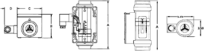
| MECHANICAL: |
|
|
|
|
DIM
|
Series
3
|
Series
4
|
Series
5
|
Series
5
|
|
A
|
6-9/16"
(167mm)
|
7-5/32"
(182mm)
|
3-1/2"
(90mm)
|
3-1/2"
(90mm)
|
|
B
|
3-11/32"
(85mm)
|
3-9/16"
(90mm)
|
10-1/8"
(258mm)
|
12-5/8"
(322mm)
|
|
C
|
3-5/32"
(80mm)
|
3-9/16"
(90mm)
|
–
|
–
|
|
D
|
1-7/8"
(47mm) |
1-7/8"
(47mm) |
– |
– |
|
Port Sizes
|
NPTF: 1/4", 3/8",
1/2"
SAE: #6, #8, #10
BSP: 3/8", 1/2"
|
NPTF: 3/4", 1"
SAE: #12, #16
BSP: 3/4", 1"
|
NPTF: 1-1/4",1-1/2"
SAE: #20, #24
BSP: 1-1/4", 1-1/2"
|
NPTF: 2"
SAE: #32
BSP: 2"
|
|
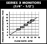
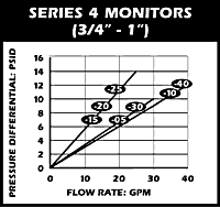
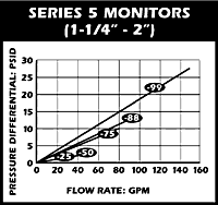
| PRESSURE DIFFERENTIAL
VS FLOW RATE: |
|
|
ELECTRONIC
TRANSMITTER PERFORMANCE:
| • |
Power
Requirements: 12-35
Vdc, connections via screw terminal |
| • |
Load
Driving Capacity:
4-20mA: Load resistance is dependent on power supply
voltage. Use the following equation to calculate maximum
load resistance: Max Loop Load (ohms) = 50(Power supply
volts - 12). 0-5Vdc: Minimum load resistance 1000 ohms.
0-1mA: Maximum load resistance 100 ohms. 1-5Vdc: Minimum
load resistance 25K ohms |
| • |
Transmission
Distance: 4-20mA,
0-1mA and 1-5Vdc: limited only by wire resistance and
power supply voltage. 0-5Vdc: <200 feet recommended.
|
| • |
Digital
Display: 3.5
digits, 0.5" digit height, LCD |
| • |
LED
Indicator:
Provides power indication, intensity increases with
flow rate |
| • |
Over-Current
Protection:
Self limiting at 35mA |
| • |
Resolution:
Infinite |
| • |
Isolation:
Inherently isolated from the process. |
| • |
Response
Time: <0.1
seconds |
|
|
|