 |
Model
Nos.
R1-120
R1-220
R1-12 |
R1
Relay-DPDT
This
relay device provides liquid level switch overload
protection for all Madison single level switches.
Input coils are available for 110 VAC, 220 VAC or
12 VDC applications. The isolated output contacts
can be used to switch a wide variety of voltages.
The peak power of the device being controlled should
not exceed the rated loads. The relay can be used
for solenoid valves, pumps and alarm applications
that do not exceed the listed ratings.
Maximum
Output Ratings:
15A @ 220 VAC
30A @ 110 VAC
30A @ 30 VDC
Dimensions:
1-5/16" x 1-3/8" x 1-9/16"
Mounting
Connection:
Easily mounted with molded-in tabs; connected via
1/4" solderable spade terminals
Temperature:
-40°C to +55°C
|
Wiring
Diagram (Switch Protection)
-
Apply one side of the input power through the float
switch and attach to terminals 7 and 8, as shown.
- Connect
one line of the switched power through pin 5 and
the desired operation terminal (pin 1 or 3) and
back through the switched device.
| Switched
Terminals |
| 1
Normally Closed |
2
Normally Closed |
| 3
Normally Open |
4
Normally Open |
| 5
Common (1-3) |
6
Common (2-4) |

| Output
Contact Ratings |
| (5-1,
5-3, or 6-2, 6-4) |
| 15A
@ 220 VAC |
| 30A
@ 30 VDC |
| 1/3
Hp @ 277 VAC |
|
 |
Model
Nos.
R2-120
R2-220 |
R2
Controller
This
controller is designed for use in pump-up or pump-down
applications, both with Madison's two-float level
switches or three probe conductivity sensor. Input
coils are available for 110 VAC or 220 VAC applications.
It is supplied with a mounting socket for wire hook
up. The isolated output contacts can be used to switch
a wide variety of voltages. The peak power of the
device being controlled should not exceed the rated
loads.
Maximum
Output Ratings:
(Socket rating is 10A @ 300 VAC)
5A @ 220 VAC
10A @ 110 VAC
10A @ 30 VDC
Dimensions:
Controller: 1-3/4" x 2-3/8" x 2-3/4"
Socket: 1-9/16" x 2" x 11/16"
Total Installed Height: 3-11/16"
Mounting
Connection: Two molded thru holes for mounting
with #8 screws or bolts; can be DIN rail mounted
|
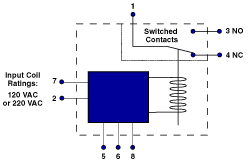
Wiring
Diagram (For Float Switches)
- Set
switches "Normally Open."
- Connect
Upper switch to pins 5 and 8, Lower switch to pins
5 and 6.
- Connect
the switched voltage to terminal 1 (AC or DC Volts).
- FOR
PUMP-UP: Connect one end of the pump/valve to terminal
4 and the other end to the switched voltage return.
FOR PUMP-DOWN: Connect one end of the pump/valve
to terminal 3 and the other end to the switched
voltage return.
- Connect
line voltage to terminals 2 and 7.
| Output
Contact Ratings |
| (1-3
or 1-4) |
| 5A
@ 220 VAC |
| 10A
@ 120 VAC |
| 10A
@ 30 VDC |
|



 Madison
Company offers Relays and Controllers for use with our
Float Switches and Conductivity Switches. Relays are
used for switch overload protection and for solenoid
valve, pump and alarm applications. Controllers are
used in pump-up or pump-down applications.


